
Compressor condensate is not simply water from an automatic drain: it can contain free oil, emulsified oil, dissolved contaminants and process chemicals. By the end, you will be able to estimate the liquid load, compare treatment technologies, and prepare the site data needed to choose a system that matches your Tumkur factory’s equipment and discharge route.
Key takeaways
- Measure condensate flow during the wettest production conditions.
- Match treatment technology to lubricant type, oil concentration and contamination.
- Account for Tumkur’s rainfall, temperature, drainage rules and available service space.
- Specify outlet limits, sampling points, alarms and a documented maintenance schedule.
What compressor condensate contains before it reaches a drain
Atmospheric air carries water vapour into every compressor. Cooling in the aftercooler turns that vapour into liquid, which collects in the receiver, particulate filters, coalescing filters and refrigerated- or desiccant-dryer drains. Oil-injected screw and reciprocating compressors add lubricant to this water through the compression chamber, seals and carryover.
- Free oil forms a visible layer that gravity can separate.
- Dispersed oil exists as fine droplets and needs coalescence.
- Emulsified contaminants stay mixed because detergents, corrosion inhibitors, coolant carryover or synthetic oils stabilise them.
- Dissolved pollutants include soluble lubricant components, additives and metals that remain after visible oil is removed.
A timer drain and a zero-loss drain only remove collected liquid from the compressed-air system. They do not make that liquid safe for a floor drain or stormwater line. Keep oil-free compression, food-grade lubricant and synthetic-lubricant condensate identified as separate waste streams until testing confirms compatibility.
Do not automatically mix vacuum-pump condensate, process-cooling blowdown, wash water or cutting-fluid spills with compressor condensate. Detergent or metalworking fluid can turn separable oil into an expensive stable emulsion.
For laser-cutting machines, liquid-waste treatment is separate from ISO 8573-1 air-quality control: specify particle, water and oil classes at the machine inlet, then use dryers, filters and sound distribution design to deliver that air.
How to calculate the compressor condensate separator size
Size the compressor condensate separator for the maximum liquid volume reaching it during the design interval, not for the compressor nameplate or catalogue air-flow rating. A separator sized from average drain volume can overflow during monsoon operation, start-up or a dryer drain dump.
1. Record each compressor’s operating hours, actual loading pattern, free-air delivery in m³/min, inlet temperature, relative humidity and operating pressure. Treat FAD as an indirect input: two compressors with equal FAD can produce different condensate volumes because their loading, inlet conditions and cooling differ.
2. Calculate inlet water content from temperature and relative humidity, then calculate the water remaining in compressed air at the separator inlet using pressure and aftercooler outlet temperature. Water condensed is approximately inlet water content minus water remaining at that point, multiplied by actual loaded air volume and operating time.
3. Add measured discharge from every receiver, particulate or coalescing filter, refrigerated-dryer drain and desiccant-dryer drain. Record timer-drain or zero-loss-drain volumes separately; include dryer regeneration and dump cycles rather than averaging them away.
4. Set the compressor condensate separator size from the peak simultaneous liquid flow and total design-interval volume, with buffer capacity for start-up, high condensate temperature and Tumkur’s humid monsoon conditions. Use drain measurements to validate the moisture balance.
5. Ask for rated condensate capacity, maximum inlet temperature, allowable pressure, oil concentration and test assumptions. Do not accept a catalogue m³/min air rating as wastewater capacity; require the assumptions behind that rating.
Which treatment technology matches the lubricant and contamination
Choose by the contaminant in the drain, not by the equipment label. The correct treatment technology depends on whether you have collected liquid, airborne oil, stable emulsion or biodegradable wastewater.
| Option | Designed to remove | Use it when |
|---|---|---|
| Dedicated oil-water separator | Free and dispersed oil through gravity, coalescence and adsorption or other media | Treating compressor condensate from oil-injected equipment |
| Coalescing filter | Liquid droplets from compressed air or a liquid stream | Separating droplets as a process stage, not proving final wastewater compliance |
| Oil mist eliminator | Airborne oil droplets | Controlling mist at a compressor or vent, not collected drain liquid |
| Biological treatment unit | Biodegradable dissolved or emulsified contaminants | The feed is compatible and temperature, pH, oxygen and residence time are controlled |
| General wastewater treatment plant | Waste defined by its engineered process | Its design and discharge consent specifically accept compressor condensate |
Gravity separation alone removes a floating oil layer, then fails on stable emulsions formed by detergents, corrosion inhibitors, coolant carryover or some synthetic oils. Mixing wash water or cutting fluid into compressor drains can create that emulsion.
Specify lubricant compatibility before approval: mineral oil, PAO, ester and polyglycol formulations behave differently. For an oil water separator for factories, require treated-effluent testing with the actual lubricant, documented media life and a disposal route for concentrated oil and spent media.
Keep food-grade lubricant and oil-free compressor streams separate until testing confirms compatibility. Treat them as different waste streams, not as reasons to call every filter an oil-water separator.
How Tumkur conditions and site data determine the selection
Tumkur’s warm compressor room and monsoon humidity must become design inputs. Use seasonal peak relative humidity, compressor-room temperature, daily operating hours, compressor count and peak simultaneous loading—not the nameplate alone. A dry-season drain measurement can undersize treatment when monsoon moisture rises.
Condensate treatment system selection is a fit between waste chemistry, peak liquid volume, treatment guarantee and the legal discharge path. Which condensate treatment system fits a factory in Tumkur depends on that complete match.
| Option | Design approach | When it applies |
|---|---|---|
| One separator | Common collection and treatment | Compressors use compatible lubricants and other drains are excluded |
| Separate treatment | Isolated headers and units | Oils, vacuum-pump condensate or process equipment streams differ |
| Composite testing | Laboratory characterisation before selection | Several streams must be combined and their chemistry is uncertain |
Use one separator only after confirming lubricant compatibility and a stable waste stream. Keep different lubricant types, vacuum-pump condensate and process-equipment drains separate; otherwise run a composite waste-characterisation test before accepting a supplier’s capacity guarantee.
Record these site inputs:
- Compressor model and kW; FAD in m³/min; pressure; lubricant name and formulation
- Drain type and count; condensate temperature; receiver, aftercooler, filter and dryer arrangement
- Actual operating schedule, peak simultaneous loading and storage volume
- Proposed discharge route
Request the Karnataka State Pollution Control Board consent conditions and the wastewater operator’s acceptance criteria. Do not assume one oil limit applies to every route or factory location. A site survey by Airprax Pneumatics LLP can turn these records into a drain-by-drain design basis, including peak moisture and treatment capacity.
Related product
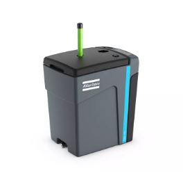 | Compressor Products Airprax Pneumatics LLP, Bangalore, provides reliable condensate treatment solutions designed to efficiently separate and remove oil, contaminants,... View product → |
What to specify, test and maintain before discharge
Specify the installation around a contained waste path, not the compressor drain outlet. Use a dedicated collection header with isolation valves, low-point collection or buffer capacity, lubricant-matched treatment, final polishing where required, a sample port and a high-level alarm.
1. Require the supplier to design for normal and upset conditions: hot, humid operation; maximum simultaneous compressor loading; dryer regeneration or drain dumps; start-up; high condensate temperature; and blocked or exhausted media. Any bypass must discharge into contained collection, never an open floor drain or stormwater line.
2. Make the procurement package include a P&ID, drain-by-drain design flow, maximum pressure and temperature, rated condensate capacity, lubricant compatibility, media replacement interval, alarm logic, and a safe isolation procedure that cannot contaminate the compressed-air network.
3. Specify commissioning samples and laboratory tests for oil and grease. Add COD, pH, suspended solids and relevant metals when the consent requires them. EPA Method 1664B is one named method for n-hexane extractable material, but follow the method and limits in the current Karnataka consent.
4. Record spent adsorbent, concentrated oil and rejected condensate as controlled waste, with disposal documentation. Do not treat clear-looking effluent as compliant; appearance cannot reveal dissolved or finely dispersed contamination.
5. Schedule service checks for blocked drains, high-level alarms, exhausted media, sample results and seasonal monsoon loading. Test alarms by simulation, inspect each drain strainer and confirm that the outlet still leads to the approved discharge route.
Frequently asked questions
What does compressor condensate contain before treatment?
It contains water from atmospheric humidity, lubricant from oil-injected compressors, compressor wear particles, pipe scale, filter residue and dissolved contaminants.
How do you calculate compressor condensate separator size?
Use the highest measured or calculated condensate volume from all drains, then size the separator for peak flow rather than the daily average.
Which treatment technology should a factory choose?
Select the technology according to the lubricant and contamination: coalescing oil-water separators suit many mineral or synthetic oils, while emulsified condensate may require chemical or membrane treatment.
What should a Tumkur factory check before discharge?
Check local discharge conditions, sample the treated outlet, confirm the oil concentration limit, provide a sampling point and document filter replacement and waste handling.